Unified Modeling Language
The Unified Modeling Language (UML) has emerged as the standard notation for OOAD.
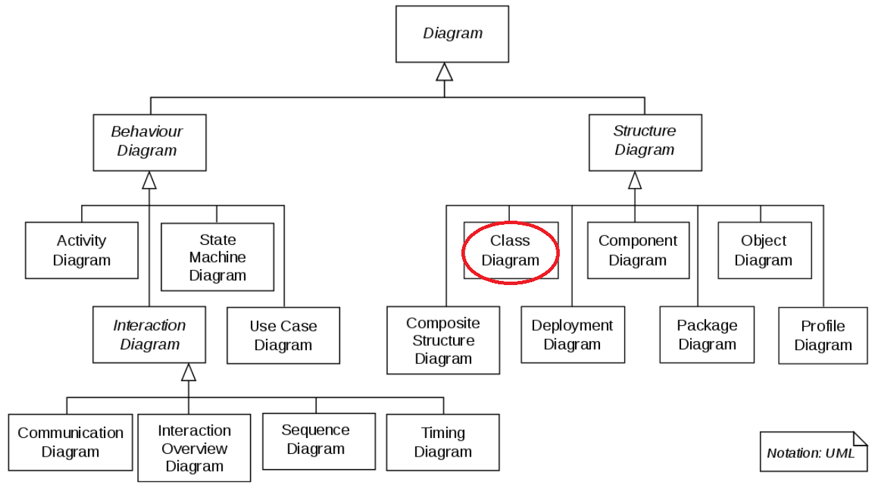
UML has many types of diagrams, each aimed to either describe the structure or the behavior of the software system. The most commonly used is the Class diagram employed to illustrate a software system's necessary classes and their relationships.
info
You must produce a UML Class diagram for your project and keep it updated at each iteration. The diagram gives us an overall view of your software system more effectively than either a natural language or a programming language can.
info
IntelliJ IDEA Ultimate Edition comes with a diagramming utility that can convert your code to UML diagram. You may use this tool if you wish.
caution
If you use a tool to automatically generate UML class diagram from your source code, make sure you can read and understand it. We will be using UML for describing design principles in lecture and related design questions on the exam (quiz).
Class
In a Class diagram, each class is represented as a box. The box contains a class's name.

It can optionally include attributes (data fields), and operations (methods).

The name of the class is the only required tag in the graphical representation of a class. It always appears in the top-most compartment.
Attributes appear in the second compartment just below the name-compartment. They are presented as name: type and they can be preceded by the following signs to indicate their visibility: + (public), - (private), # (protected), / (derived).
Operations appear in the third compartment. They are presented as method(type): return_type; you can specify the visibility of an operation in the same way you would for an attribute.
tip
When depicting classes
- Static methods and fields are indicated by underlining.
- Constant (i.e. final) fields are indicated via naming convention: in ALL_CAPS.
- Abstract methods are shown in italics, where permitted by the font in use.
When drawing a class, you don't need to show (all) attributes and operations. Typically, you omit from the box such common operations as constructors, get methods, and set methods.
Relationship
There are three kinds of relationships in UML Class diagram:
- dependencies
- associations
- generalizations
We use a line (connector) to show a relationship. Different relationships are depicted differently (e.g. dashed vs solid line, arrow vs diamond head, etc.); so, pay attention to the depiction of relationships in the examples that follow.
Dependency Relationships
A dependency shows a class (somehow) uses the other one.
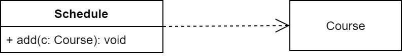
The dependency from Schedule to Course exists because Course is used in the add operation of Schedule.
A dependency may also indicate a semantic relationship between two classes.
Association Relationships
Association is used to model objects that contain other objects. Here a class holds a data field reference to the other class. For example, Course has a (field of type) Instructor:
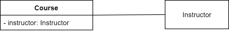
Association represents has-a relationship. It is represented by a (solid) line between two classes.
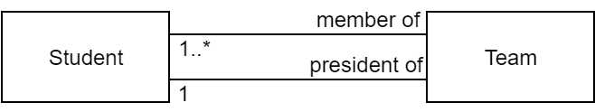
We can indicate the multiplicity of an association by adding multiplicity adornments to the line denoting the association.

The above example indicates that a Course has one Instructor.

The above example indicates that an Instructor is associated with (teaches) one or more Course.
We can indicate the the role of an object in an association using role names.
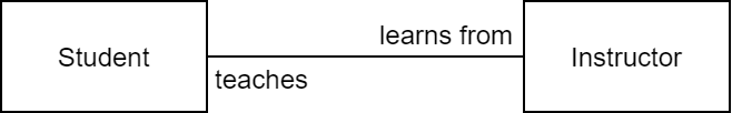
We can also name the association.

We can specify more than one association on a pair of classes.
We can constrain the association relationship by defining the navigability of the association.

Here, a Router object requests services from a DomainNameServer object by sending messages to (invoking the operations of) the server. The direction of the association indicates that the server has no knowledge of the Router.
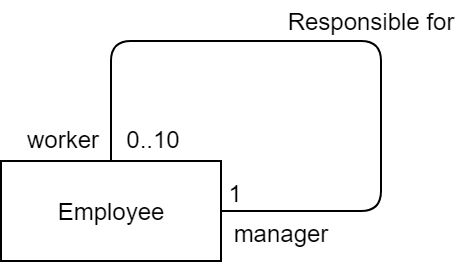
A class can have a self association.
Finally, there are special associations called aggregations and compositions.
Aggregation
An aggregation specifies a whole-part relationship between an aggregate (a whole) and a constituent part, where the part can exist independently from the aggregate. Aggregations are denoted by a hollow-diamond adornment on the association.

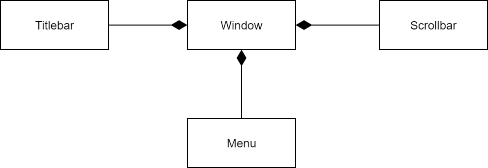
Composition
A composition indicates a strong ownership and coincident lifetime of parts by the whole (i.e., they live and die as a whole). Compositions are denoted by a filled-diamond adornment on the association.
Generalization Relationships
A generalization specifies "is a kind of" (or simply is-a) relationship. It is most commonly used to depict any inheritance hierarchy.
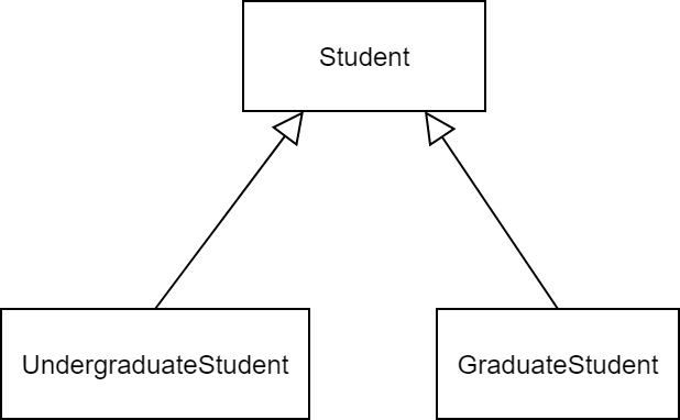
The above example shows that the classes UndergradStudent and GradStudent are each derived from the class Student.
Generalization is represented by an arrow with a hollow head points to the superclass. If a class implements an interface, you draw an arrow having a dotted shaft and hollow head from the class to the interface.

info
Abstract classes and interfaces may be shown using the textual annotation <<abstract>> and <<interface>> above or below their name.